
Game Boy Advance V2 IPS Installation Guide
God of Gaming - Game Boy Advance V2 IPS KIT INSTALLATION GUIDE

FLUSH CUTTER & MOTHERBOARD NOT INCLUDED
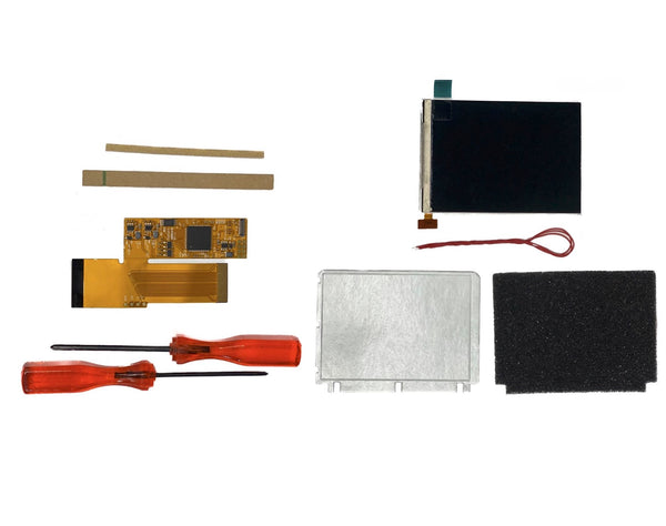
Products Used:
Game Boy Advance V2 IPS Full Mod Kit
STEP 1: Remove the 6 long screws and small bottom screw. We recommend keeping the original screws whenever possible. The screws that come in the kit are better used for replacements for broken or missing screws.


STEP 2: Remove the 3 small inner screws (Some may only have 2 that is normal). Save these original screws as well.

STEP 3: To separate the motherboard from the LCD, lift the 2 side notches and then lift the ribbon out of the port.


STEP 4: (Optional) You may need to trim the shell if you are using your original shell or purchased a shell without it being pre-trimmed. Use a flush cutter to trim down what is highlighted below. Make sure there are no sharp points that can damage the LCD.

STEP 5: Place the adhesive sticker along the frame of the front of the shell.

STEP 6: Remove the adhesive cover and place the 2 plastic separators on the area indicated below. Some Pre-trimmed shells come molded with brackets already on them. If that is the case then this step is not necessary. This is only necessary if your shell is hand-trimmed.


STEP 7: Place the LCD on the shell and place the insulating film over the back of the LCD (Make sure to place because it can cause issues.)


STEP 8: Add the A,B, and D-Pad buttons, LED diffuser (Circled), and clip in the ribbon onto the LCD. Make sure it is fully clipped together or it may cause issues.

STEP 9: Add pads to backs of the buttons and the Start and Select pads.

How to figure out if you have a 32 pin or a 40 pin:

STEP 10: Attach the motherboard onto the ribbon cable. Make sure the ribbon cable is fully inserted and the side notches are both push down fully.


STEP 11: (Optional - Soldering) This part is optional if you do not want to solder the controls for brightness adjuster. If you decide not to the LCD will be stuck in the middle brightness setting.
Flip the shell and motherboard open as seen in the picture and solder the points using the soldering wire as shown in the picture. The ‘SEL’ is soldered to the front of the board at point ‘TP2’ The ‘L’ and ‘R’ is soldered to the back of the motherboard as shown in the picture. They are soldered to the upper left point of the respective trigger.

STEP 12: Flip the motherboard closed over the shell and make sure the wires don’t cross any screw holes. Screw in the motherboard with the short screws at the 3 points shown below.

STEP 13: Place the power switch, side bumpers, and the L and R triggers as shown below.

STEP 14: Attach the back plate of the shell and we recommend you test the system now before you close it up. Screw in the big screws in at the spaces shown below. Make sure for the screw in the battery compartment (green circle) you use the smaller screw as a big screw may damage the shell.

STEP 15: Attach the lens and make sure the LCD is free of dust before installing since removing the lens can be difficult.
EXTRA: Here is how to adjust the brightness of the IPS LCD.

If you have any other questions, please feel free to contact us at sales@godofgaming.com