
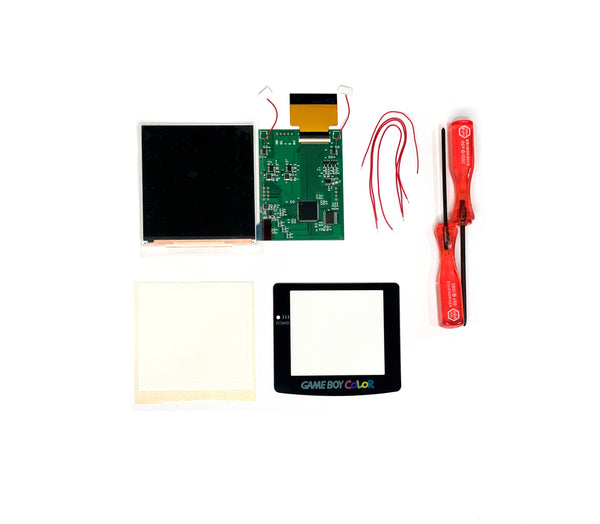
Game Boy Color Q5 IPS Backlight Mod Installation Guide

STEP 1: Remove the 6 tri-wing screws with a Y2 tri-wing screwdriver. DO NOT THROW AWAY SCREWS.

STEP 2: Remove backplate and you will see 2-3 screws holding down the motherboard. With a 00 Phillips screwdriver remove them and put them to the side.
NOTE: You should have 6 long screws and 2-3 short ones. DO NOT toss them as you will need them. The replacement screws are only meant for any lost/stripped screws.


STEP 3: Now you will remove the motherboard from the shell and screen. GENTLY lift the tabs on the top of the ribbon connector up. You can do this with the tip of your screwdriver or your finger. Make sure not to push too hard or it can break.

STEP 4: Lift up the ribbon and remove it from the adapter. You can remove the motherboard from the system. This is the only part you will need from the original GBC.


STEP 5: Trim the shell to fit the larger LCD. The area with black marker should be trimmed. Make sure to trim any sharp edges that can damage the LCD.


STEP 6: Attach the adhesive pad to the edges of the LCD frame of the shell and remove the white protective paper, if necessary you can cut it to size to fit the trimmed area.


STEP 7: Remove the protective film on LCD and carefully place and center it in the shell Place protective film on the metal back of the LCD. Fold over smaller PCB board and center (Tapeing it down is not necessary).


STEP 8: Place motherboard over and attach the ribbon to the screen port and push each side end down to lock the ribbon cable in.


STEP 9: Flip motherboard over and solder the points circled in the picture to the PCB board.
On small PCB Board to GBC Motherboard:
Sel to P12 A to P10 B to P11 Bat to BT+

STEP 10: Tape down wires. Make sure they avoid any screw holes or anything that can cause issues when tightened.

STEP 11: On the shell side, place the buttons first and then pads on top of the screen. Make sure they go in smoothly to avoid button response issues.


STEP 12: Place insulating tape on small PCB board and fold over the motherboard into the shell. Make sure everything is lined up properly and no cables are near any screw posts/holes. Screw in the 3 screws circled in the picture with the short screws.


STEP 13: Remove the adhesive cover off the touch sensors and place them at the top of the shell in the picture shown. If you need to use the IR sensor, place it in a different location. Also place the power switch button into the power switch.

STEP 14: Usually we recommend you test the system first before closing it up. Once tested, using 6 long screws, screw the back of the shell into place


STEP 15: Remove the adhesive cover and install the glass lens, make sure there is no dust and the LCD is centered.


OSD MENU
Open: Hold Select+A+B
Close: Times Out after 10 seconds or Hold Start + B
Select/Deselect: Hold Select + A
Up: A
Down: B
Slider Less: B
Slider More: A
Select ON: A
Select OFF: B
Example:
To Toggle Pixel Effect On/Off
Open OSD Menu: Hold Select+A+B
Press B to go down on Menu to Pixel Effect To toggle option press: Select+A
To turn off Pixel Select: Press B
To turn on Pixel Effect: Press A
Tap the touch sensors to quickly change brightness and color changing modes
If you have any questions please email us at: sales@godofgamingshop.com