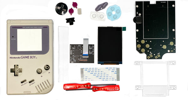
Game Boy Original DMG RIPS V5 Pro Kit Installation Guide
DMG RIPS V5 Pro Shell Kit INSTALLATION GUIDE

FLUSH CUTTER & MOTHERBOARD NOT INCLUDED
Products Used:
DMG IPS Full Mod Kit
DMG IPS Kit
Fully Built Console
STEP 1: Remove back of DMG shell with a Y2 Tri-Wing Screwdriver.
NOTE: DO NOT THROW AWAY SCREWS. [Kit comes with replacement screws, but the best ones are the OEM screws]

STEP 2: Pull down cable connecting the front motherboard to the back motherboard.
[NOTE: If you are reusing an old shell, remove front motherboard fully from shell.]

STEP 3: Remove screws from back motherboard and remove back motherboard from old shell.

STEP 4: Trimming Shell
A: Take the front of the new shell and trim off the pieces shown circled in the picture with a flush cutter. Remove any sharp angles that can poke out since this is where the LCD will be seated.


B: On the back plate of the shell, trim the small piece of plastic circled in the picture, above the small sign for ‘DC6V’. Try to make it as flush as possible, avoid any sharp pieces of plastic that may interfere with the shell closing.


STEP 5: Place centering bracket on the shell and place double-sided tape on the top and bottom side of the bracket.


STEP 6: Remove protective film on LCD and place on centering bracket. Make sure the LCD is centered and sitting properly on the centering bracket. If you need to re-adjust, be careful when removing since double-sided tape can cause damage if removed harshly.

STEP 7: Place buttons first and pads second in the shell. Make sure everything goes in smoothly so buttons work properly.


STEP 8: [NOTE: If you selected to have us pre-solder the speaker, you can skip this step]
Take the larger PCB board and the speaker and solder them together on the points shown in the picture.


STEP 9: The large PCB board will now replace the old front motherboard. Place the new large PCB board on top and install the small ribbon that comes out of the small PCB board into the port on top of the larger PCB board. Make sure the flap on the connector port is closed, to secure the ribbon. Screw in the PCB board to the shell where it is circled in the picture. Do not over tighten since it can cause button issues.
[NOTE: If you are having issues with the shell closing, scroll wheel getting stuck, or the PCB board not laying flush, trim the foam piece above the scroll wheel.

STEP 10: Place connecting cable into the back port of the front board. Then push up as much as possible. This will make sure the cable does not loosen. Most issues that occur are because the connecting cable is not properly installed.

STEP 11: Take the back motherboard and install it onto the back shell piece. Screw in where circled in the picture and place the power switch button in the power switch and the connector cap where shown in the picture.

STEP 12: Connect the connecting cable from the front motherboard onto the port in the back motherboard and push up fully. This connects the front and back motherboard fully. Make sure that the cable is fully inserted.

STEP 13: Close the two pieces of the shell and screw them back together at the screw points shown in the picture. [NOTE: Usually we recommend testing the console before fully closing together.]


STEP 14: Install self-adhesive lens on top of the LCD. Make sure everything is dust free because removing the lens once installed can be difficult.

If you have any questions please email us at: sales@godofgamingshop.com
Scroll Wheel:
Scroll Up/Down: Adjusts brightness
Press: Changes LCD Color (36 Options)

OSD MENU:
Open with Scroll Wheel
Hold: Open Menu / Close Menu
Press: Select/ Enter
Scroll Up: Up/ Option selector
Scroll Down: Down / Option Selector
OSD auto closes after 5 second inactive
