
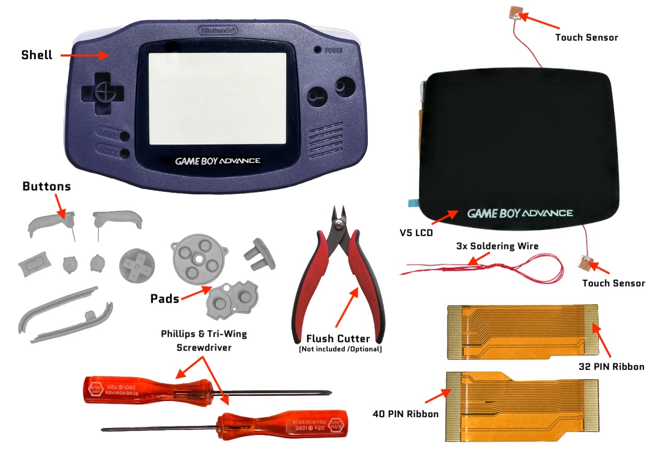
Game Boy Advance V5 IPS Installation Guide
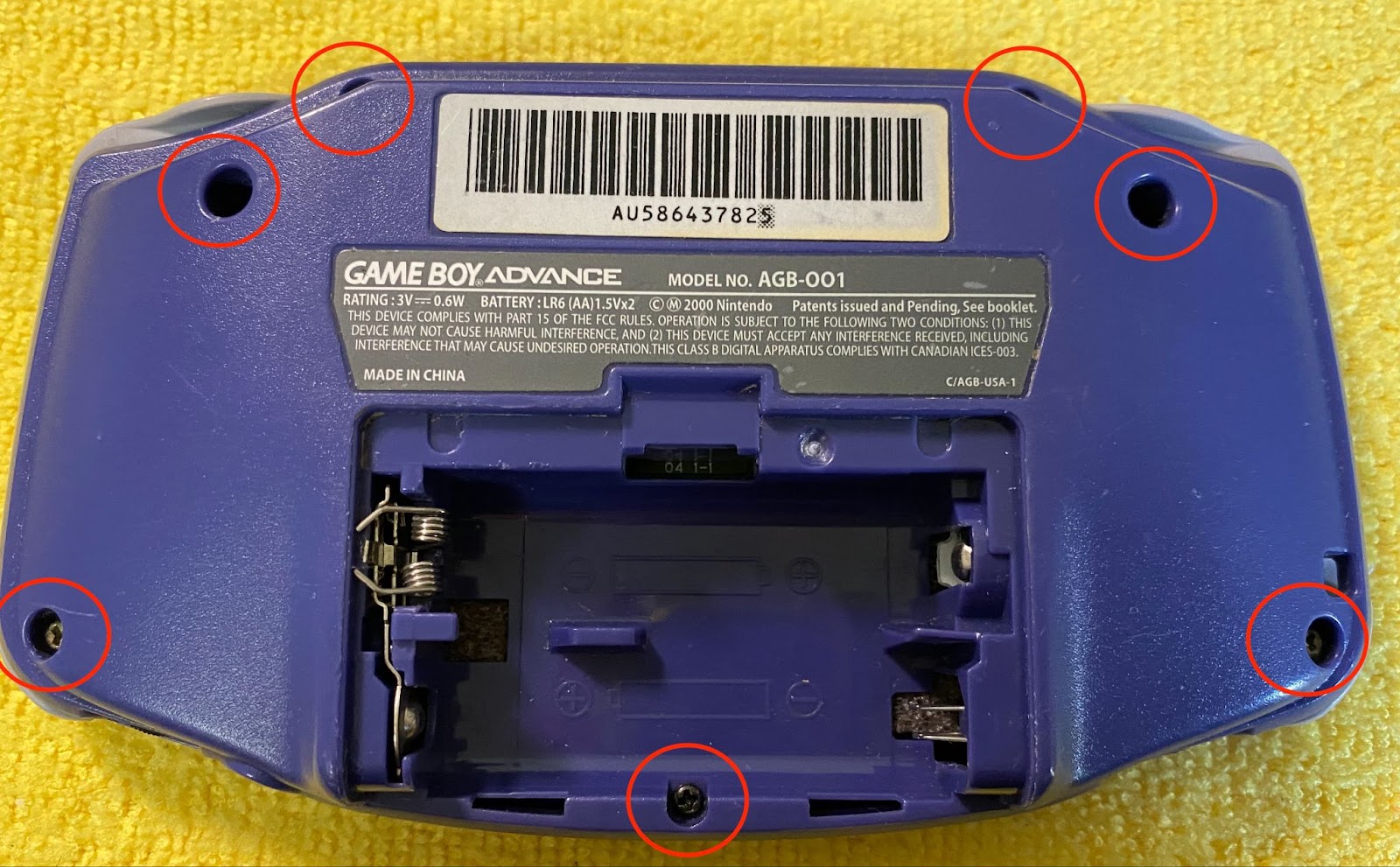
STEP 1: Remove the 6 long screws and small bottom screw.
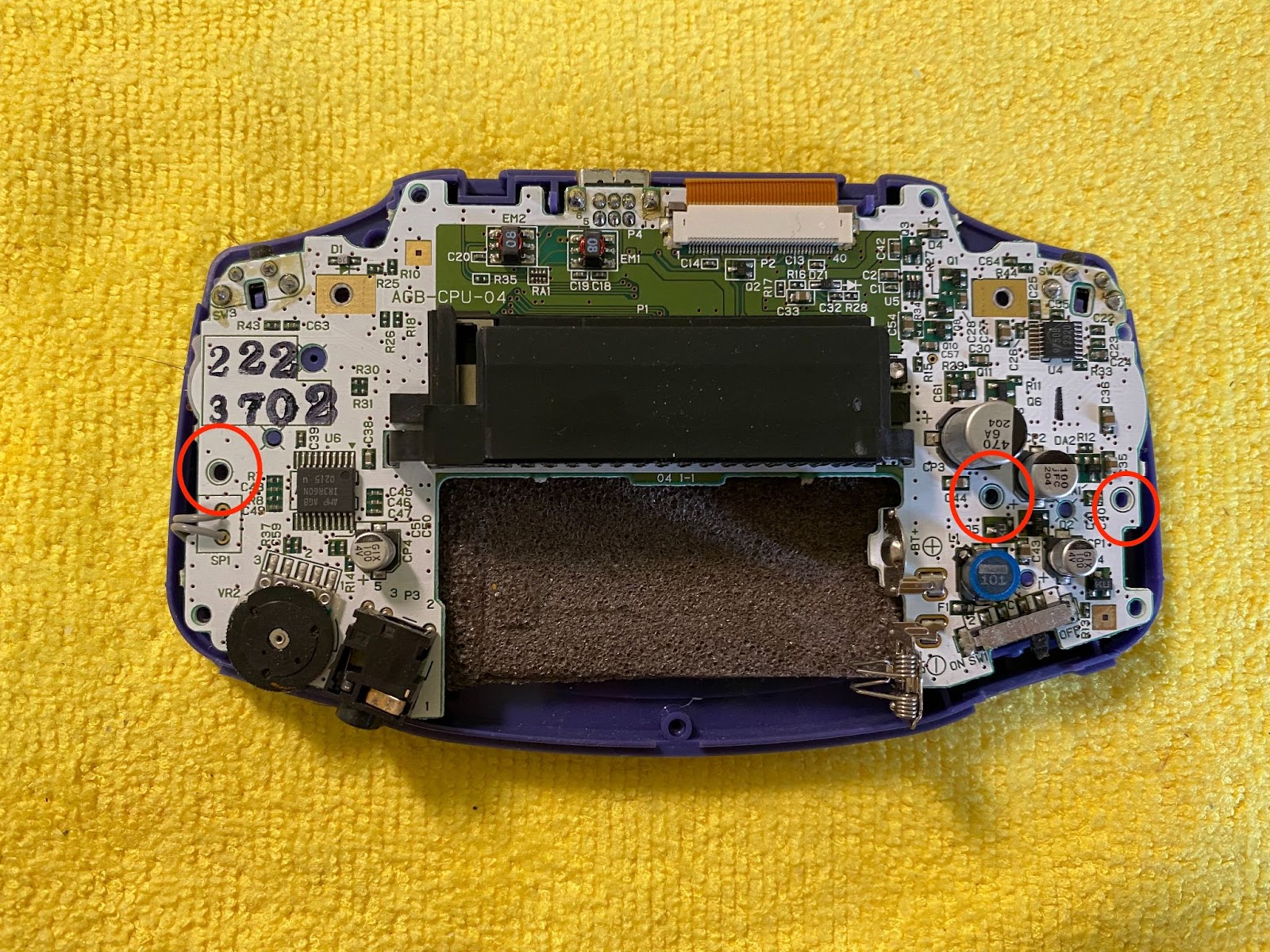
STEP 2: Remove the 3 small inner screws (Some may only have 2, that is normal).
STEP 3: To separate the motherboard from the LCD, lift the 2 side notches and then lift the ribbon out of the port.


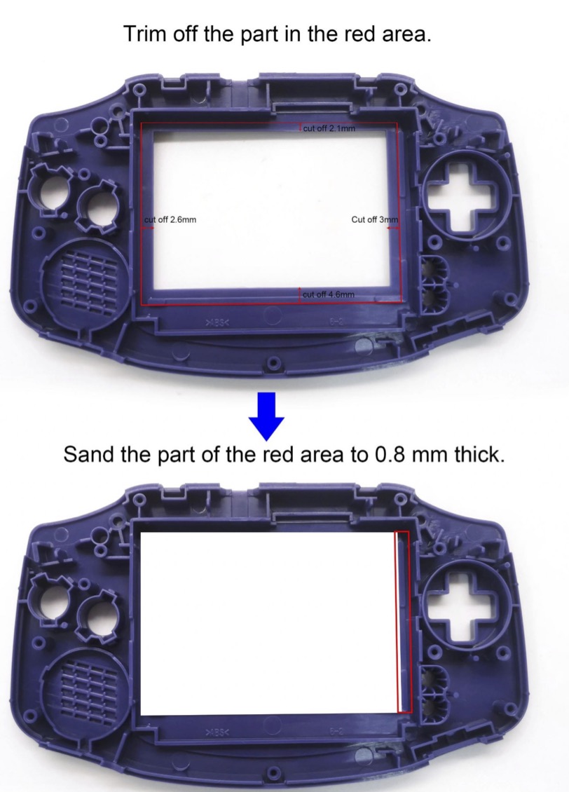
STEP 4: (Optional) You may need to trim the shell if you are using your original shell or purchased a shell without it being pre-trimmed. Use a flush cutter to trim down what is highlighted below. Make sure there are no sharp points that can damage the LCD. We offer pre-trimmed shells as well and we only recommend this method for experienced modders.
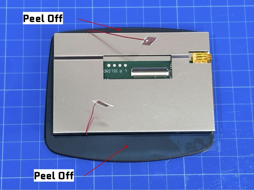
STEP 5: Starting with the V5 LCD, peel off the adhesive protector around the back of the black lens to expose the adhesive.
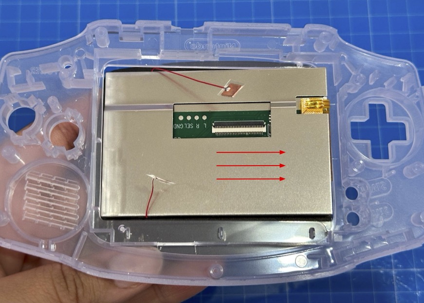
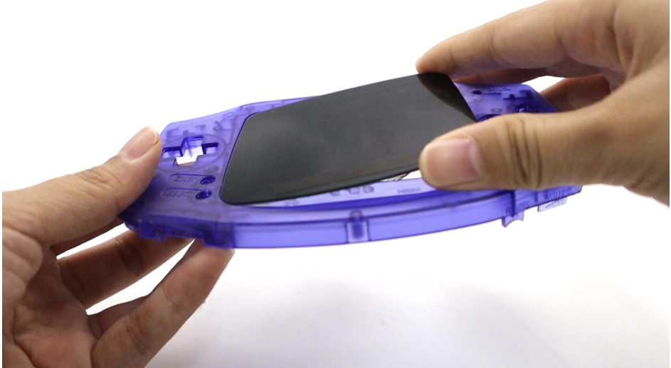
STEP 6: Insert the V5 LCD at a sight angle towards the right side of the front plate of the GBA shell and make sure it is well seated before fully placing the LCD.
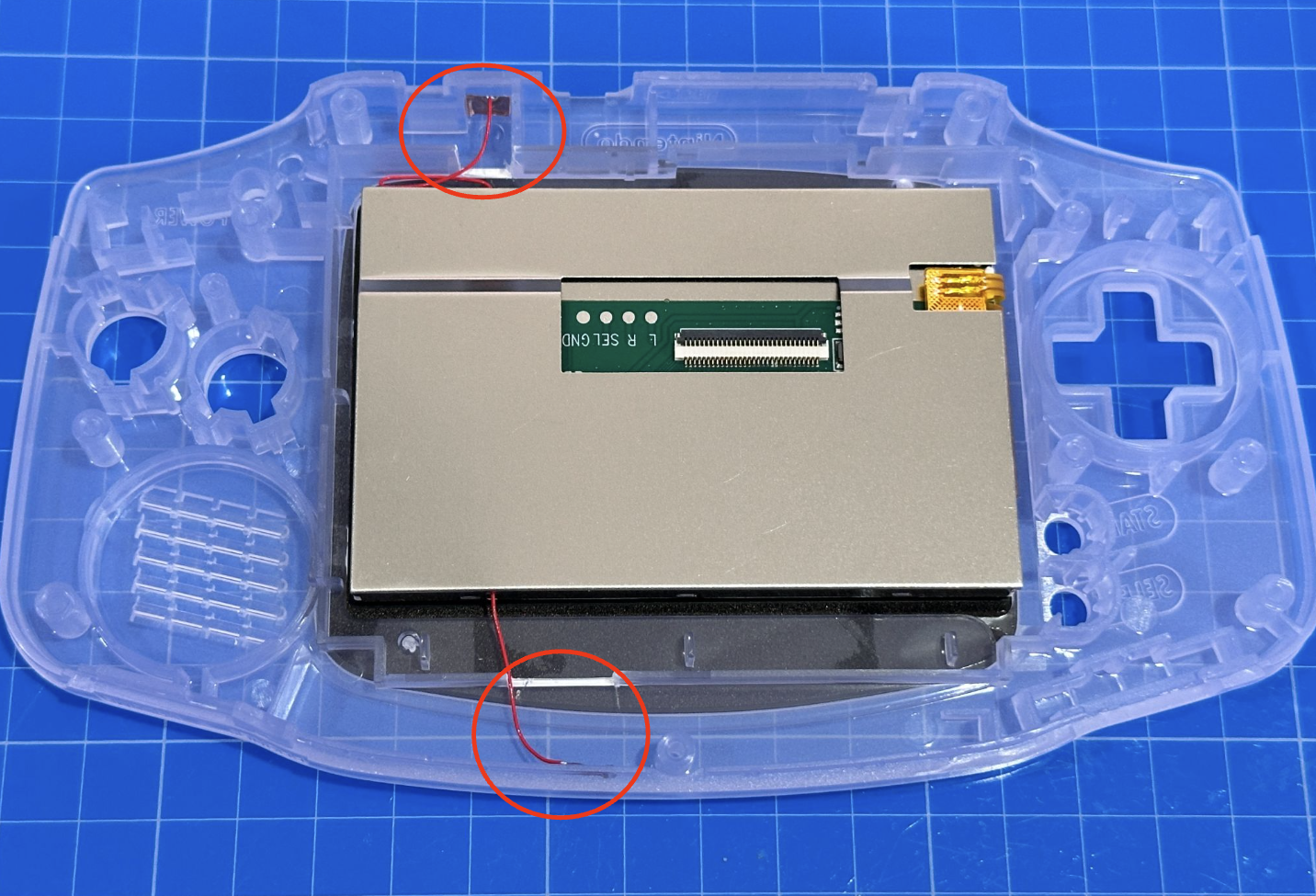
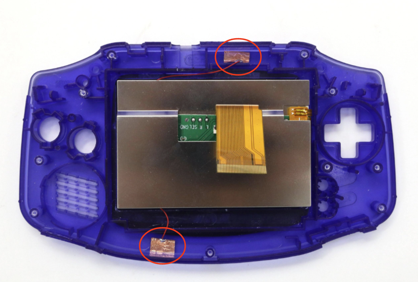
STEP 7: You should place the tap sensors on the front or side of the shell. Just remove the plastic adhesive cover so it may stick to the shell's inside. You may or may not need to trim (with a flush cutter) a slight piece of the shell away to make sure the wire has a clear path, but you may place it wherever you want. Below are some examples of where they can be placed for easy access.
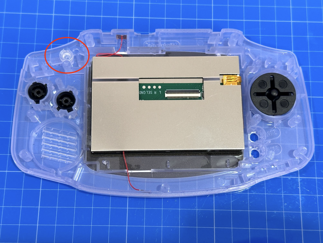
STEP 8: Add Buttons and the LED diffuser (red circle) to the shell
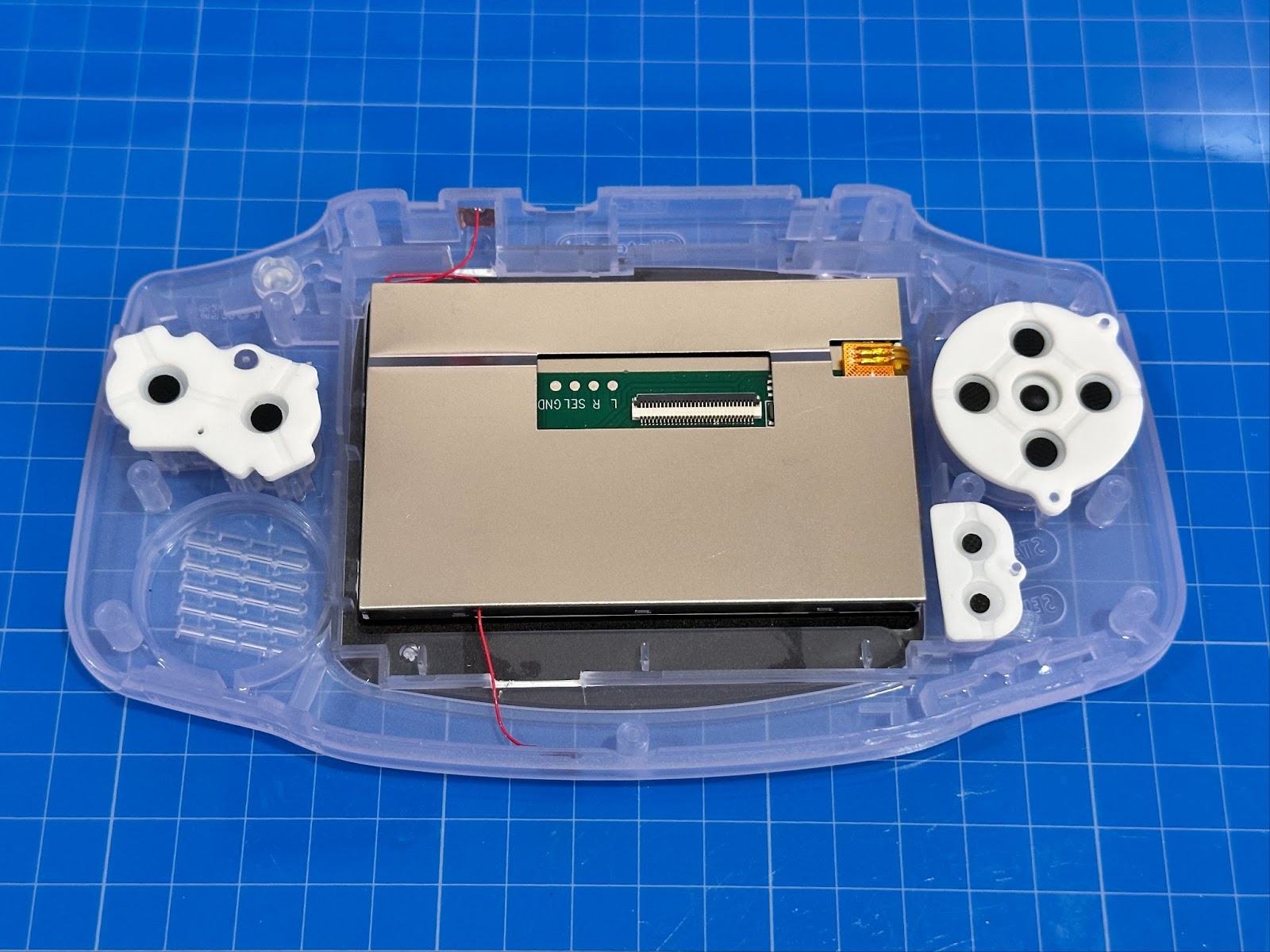
STEP 9: Add pads to the backs of the buttons and the Start and Select pads.
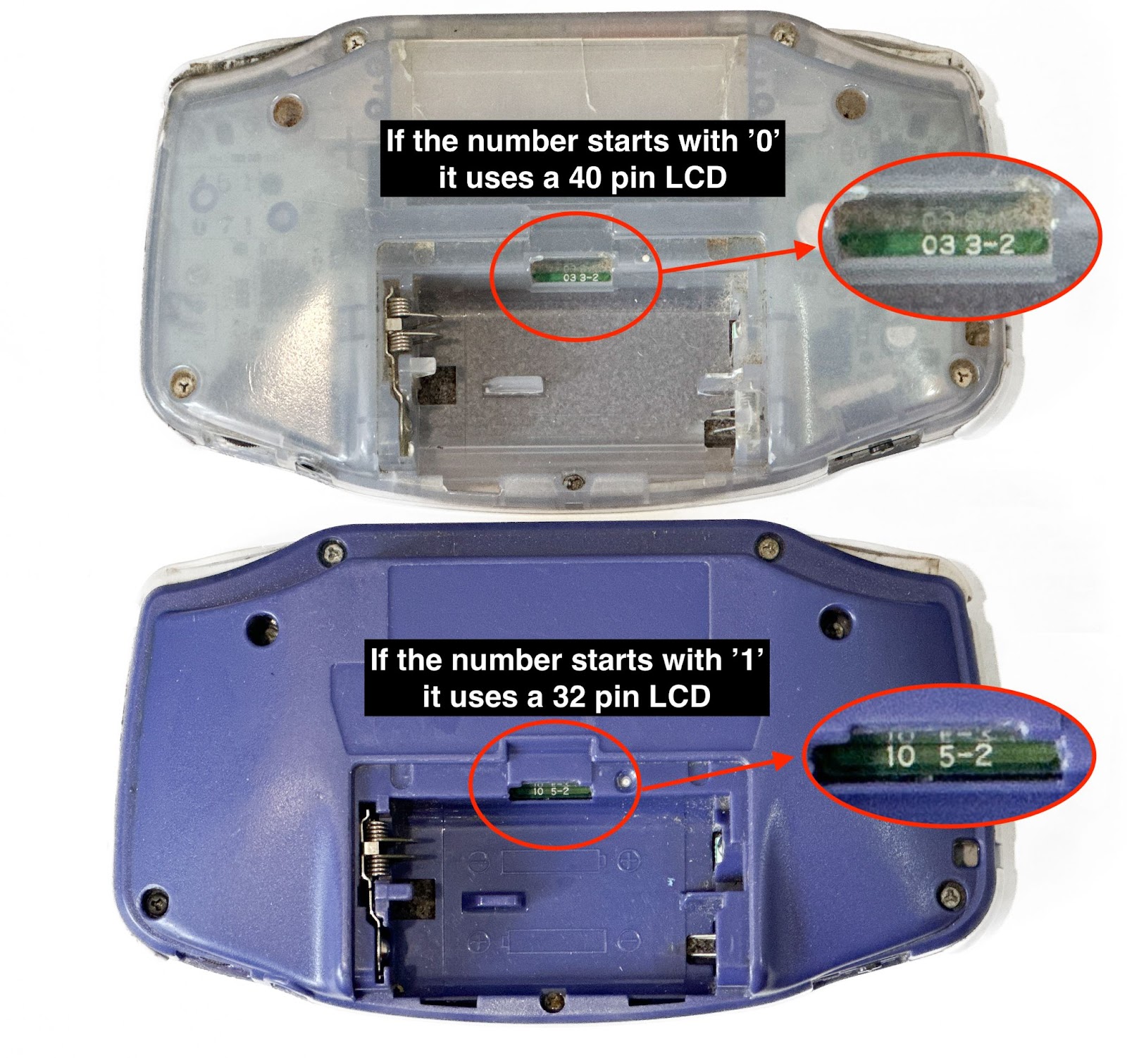
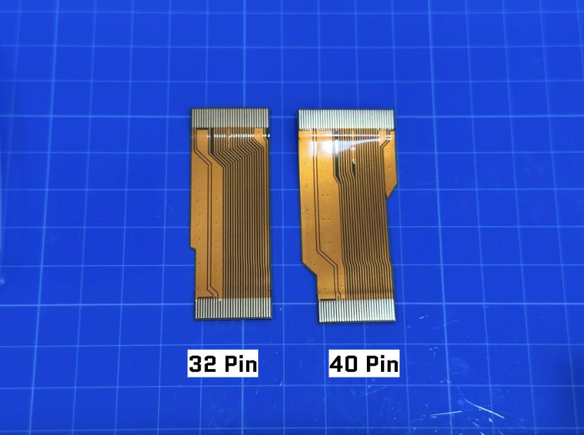
STEP 10: Choose which ribbon cable you will need for your system, both types will be included. Check the back of your GBA. If the number starts with a ‘0’ it is 40 pin. If it starts with a ‘1’ it is 32 pin.
How to figure out if you have a 32 pin or a 40 pin:
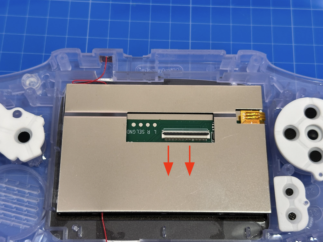
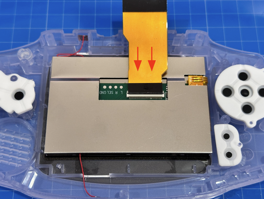
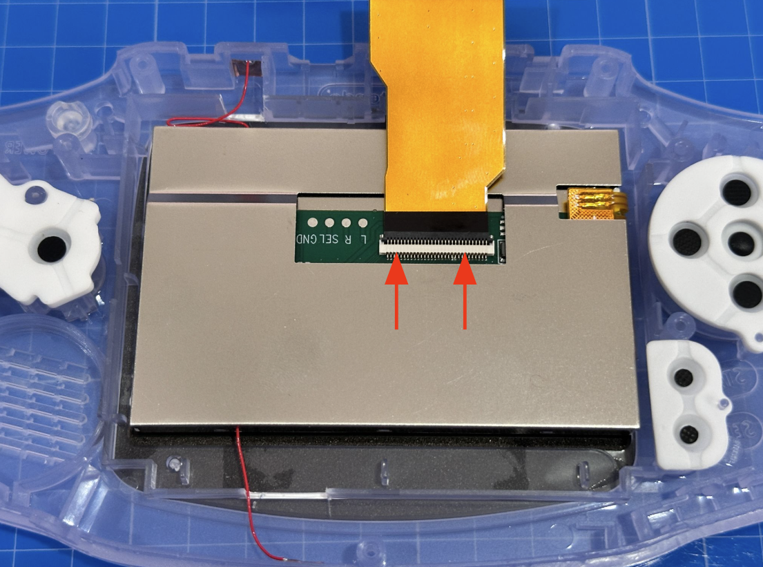
STEP 11: Insert the ribbon cable into the LCD panel by gently flipping down the black bar and fully inserting the shorter end of the ribbon cable (black side facing you) into the LCD panel. Then flip back up the black bar, locking the ribbon cable to the LCD panel.
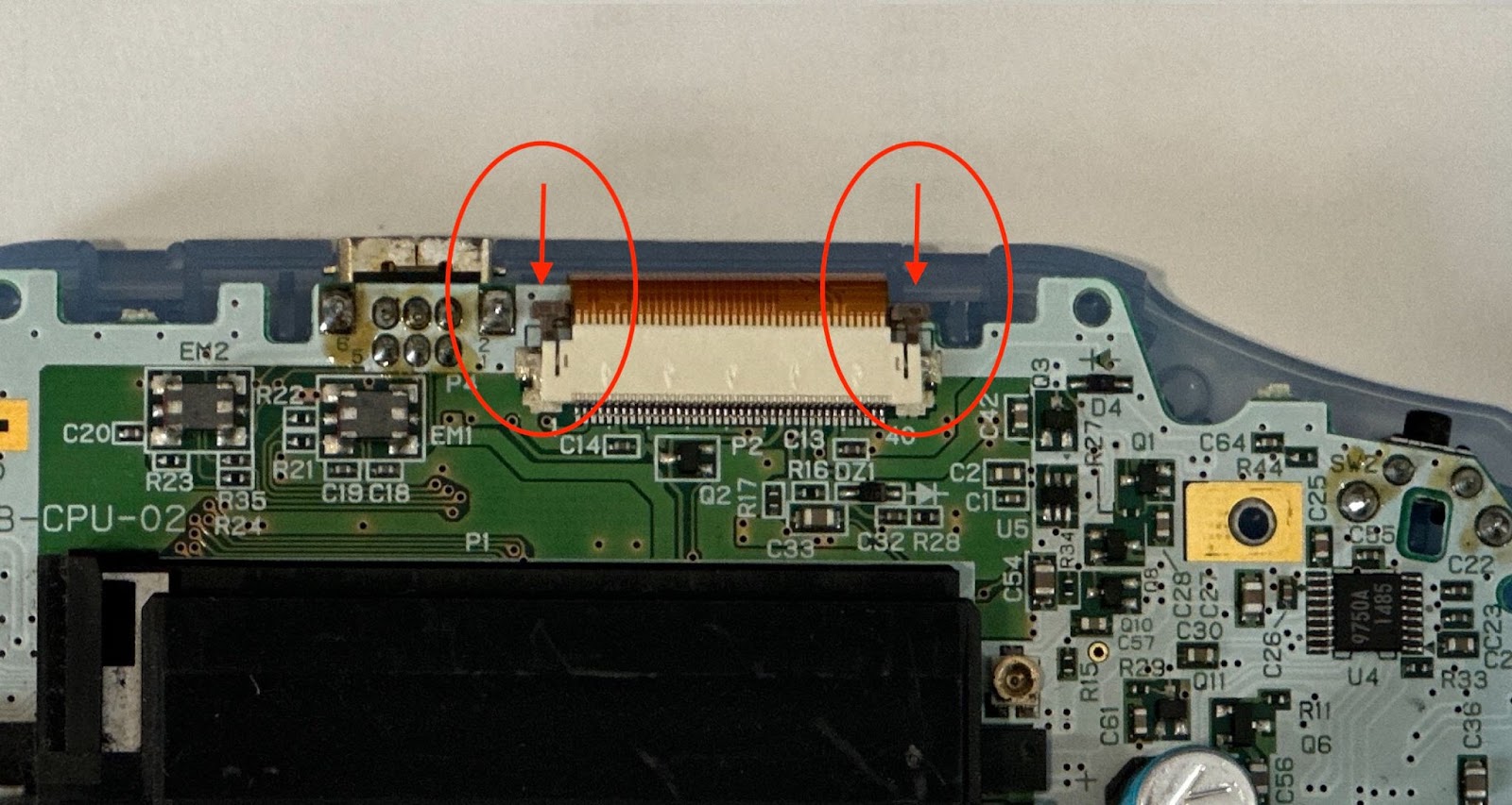
STEP 12: Attach the motherboard to the ribbon cable. Make sure the ribbon cable is fully inserted and the side notches are both pushed down fully.

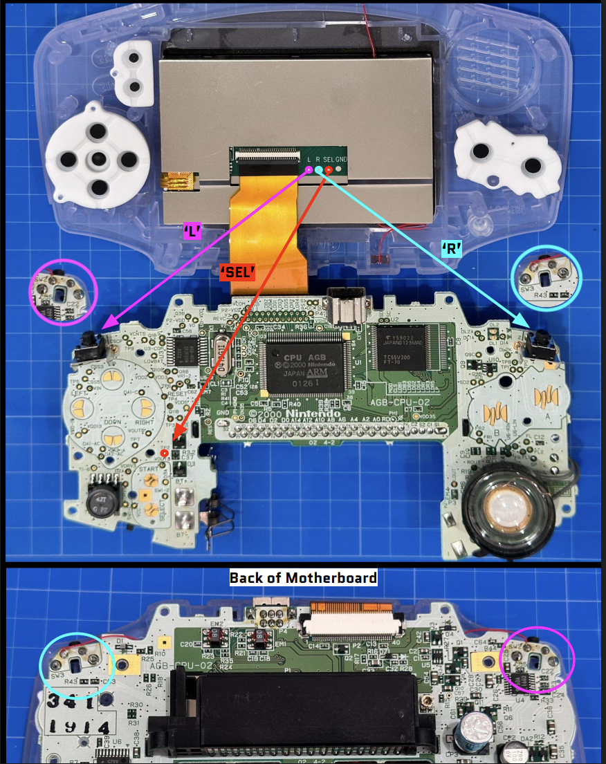
STEP 13: (Optional - Soldering) This part is optional if you do not want to solder the controls for the brightness adjuster and OSD Menu. If you decide not to solder, you will not be able to access the OSD menu but you can change the brightness by tapping the tap sensors.
Flip the shell and motherboard open as seen in the picture and solder the points using the soldering wire as shown in the picture. The ‘SEL’ is soldered to the front of the board at point ‘TP2’ The ‘L’ and ‘R’ are soldered to the back of the motherboard as shown in the picture. They are soldered to the upper left point of the respective trigger.
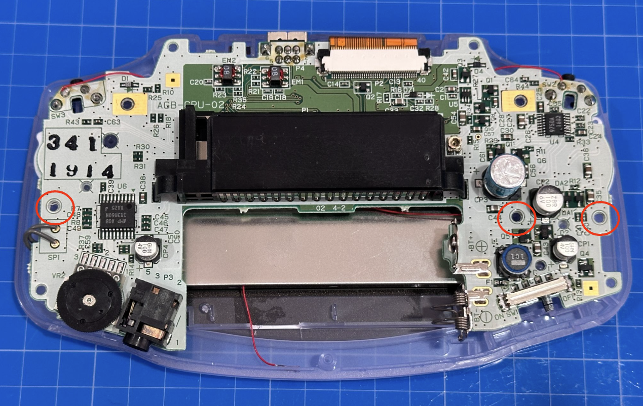
STEP 14: Flip the motherboard closed over the shell and make sure the wires don’t cross any screw holes. Screw in the motherboard with the short screws at the 3 points shown below.
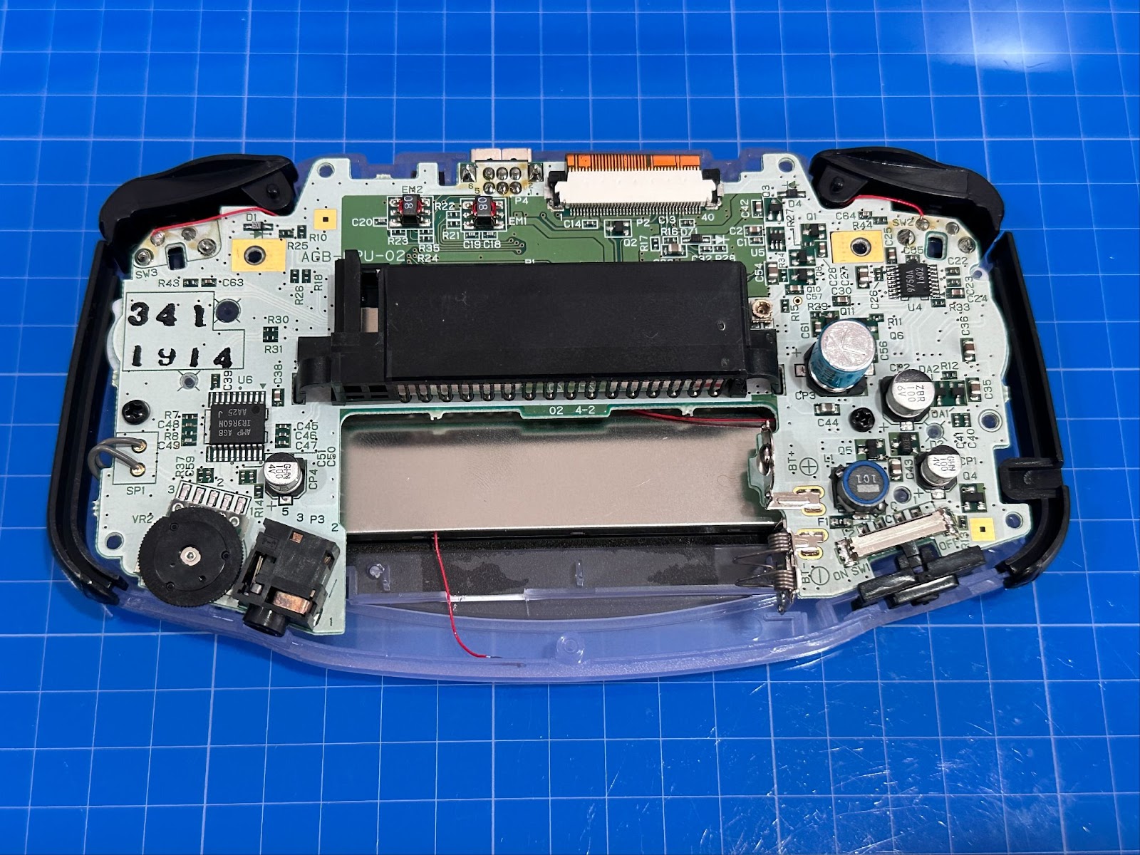
STEP 15: Place the power switch, side bumpers, and the L and R triggers as shown below.
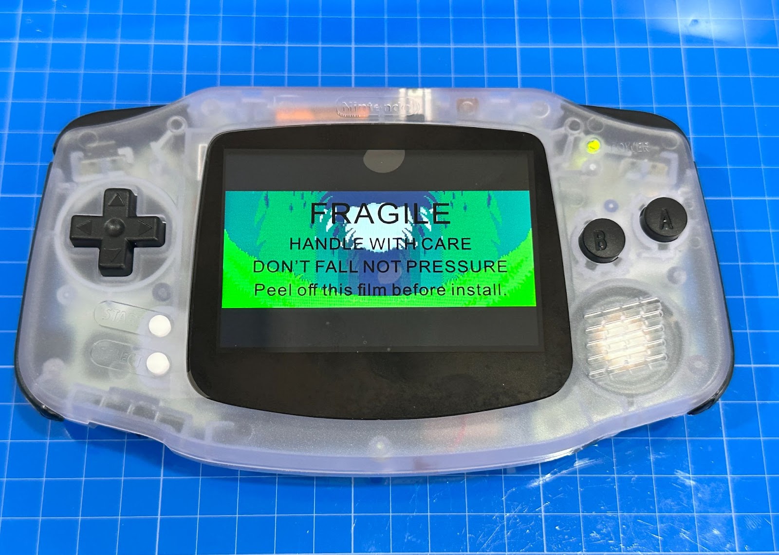
STEP 16: We recommend you test the system with a game before you close it up. Please wait until the end of the installation to remove the protective film since it helps protect the glass lens during installation.
STEP 17: Attach the back plate of the shell and screw in the big screws in the spaces shown below. Make sure to use the small screw for the battery compartment (green circle), as a big screw may damage the shell.
NOTE: Please DO NOT use the original screws with transparent shells as they may crack.

EXTRA: Here is how to adjust the brightness and access the OSD menu.

If you have any other questions, please contact us at sales@godofgaming.com